Holographic Gratings
Products
Technical Information
Grating Design Tool
Spectroscopic Properties of Gratings
Introduction
Diffraction gratings are widely used in spectroscopic instruments, for creating monochromatic light from a white light source. This is achieved by utilizing the grating’s ability of spreading light of different wavelengths into different angles. The relation between the incidence and diffraction angles, and the wavelength is given by the well known grating equation. Many of the most important spectroscopic properties, such as dispersion, resolution and free spectral range can be derived from the grating equation, from fairly straight forward algebraic manipulations.
The Grating Equation
A beam of light which falls on a grating will be diffracted into one or several beams. The directions of these beams depend on the wavelength and direction of the incident beam, and on the groove frequency of the grating.
The grating equation is a good starting point when describing the properties of gratings. The grating equation can be written:
sinα + sinβm = -mλ/d
where:
- α is the angle of incidence
- βm is the angle of diffraction. The angles are positive if they are directed counter clockwise, otherwise negative.
- m denotes the order number of the diffracted beam. m is an integer number, positive, negative or zero.
- d is the groove spacing of the grating. Usually, gratings are specified by their groove frequency given as number of grooves per millimeter. The groove spacing in nanometers is then found by taking the reciprocal of the groove frequency, and multiplying by 106.
- λ denotes the wavelength of the light in the medium surrounding the grating, usually air. λ= λ/n where λ = wavelength in vacuum, and n= refractive index.
Diffraction orders
By considering the case when m=0, the equation reduces to α=β0 or the law of reflection. There will always be this solution and therefore a reflected beam, which usually is not wanted. The reflected beam is the major cause of light losses in a grating. The diffracted order with m = -1 is the order normally used in monochromators, spectrographs, and spectrometers.
Gratings with low groove frequency will generate many diffracted orders. For monochromatic light, e.g. from a laser, a grating may be used as a beamsplitter, for generating two or more beams. Two beams may also be combined at a grating surface.
Dispersion
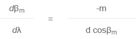
The angular dispersion is the amount of change of diffraction angle per unit change of the wavelength. It is a measure of the angular separation between beams of adjacent wavelengths. An expression for the angular dispersion can be derived from the grating equation by differentiating, keeping the angle fixed.
High dispersion can be achieved either by choosing a grating with a high groove frequency, or by using a coarse grating in high diffraction order.
Generally a fine pitch grating would be preferred because of the larger free spectral range (see below).
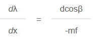
The wavelength dispersion at the exit slit of a spectroscopic instrument is usually specified as reciprocal linear dispersion, given in nm/mm. If the focal length of the instrument is f, then the reciprocal linear dispersion is given by:
The size of the instrument depends on the focal length of the optical system. By choosing a holographic grating with a high groove frequency, the instrument could be made more compact.
Free Spectral Range
As we can see from the grating equation, light of wavelength λ in the first order is diffracted in exactly the same direction as light of wavelength λ/2 in the second order, as well as λ/3 in the third order etc. When using gratings, it is therefore important to restrict the wavelength interval in some way, either by using a bandpass filter, or by making use of the limited wavelength range of the light source or the detector.
The free spectral range of a grating is the largest wavelength interval in a given order which does not overlap the same interval in an adjacent order. If λ1 is the shortest wavelength and λ2 is the longest wavelength in this wavelength interval, then the free spectral range may be expressed by:
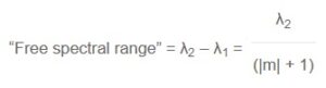
Evidently the free spectral range is reduced when the grating is used in higher orders. In -1 order, the free spectral range is λ2/2, i.e. the grating can be used from λ1 to 2 x λ1 without overlapping from the 2 order diffraction.
Resolution
The spectral resolution of an instrument is determined by the separation (Δλ) between two spectral peaks that can just barely be detected as separate with the instrument.
A theoretical treatment of the instrumental resolution shows that the properties of the grating sets the ultimate limit for the resolution. The gratings described by its “resolving power” which is a dimensionless number, R. The simplest definition is:
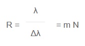
where m is the diffraction order and N is the total number of grooves on the entire grating surface. Note, however, that the grating equation places restrictions on the possible combinations of m and N.
The measured resolving power of a real grating is less than the theoretical value if the grating surface or the grating grooves are deviating from the ideal shape and position.
As an example, a 110 mm wide grating with 1800 grooves/mm, used in first order diffraction, has a theoretical resolving power of 198 000 which implies a wavelength resolution of 0.003 nm at 500 nm wavelength.
Efficiency
The absolute efficiency is defined as the amount of the incident flux that is diffracted into a given diffraction order. The relative efficiency is related to the reflectance of a mirror, coated with the same material as the grating, and it should be noted that the relative efficiency is always higher than the absolute efficiency.
For most applications only one diffraction order is used, and one would like all the diffracted light to go into that order giving an absolute efficiency of 100% for all wavelengths. However, the grating efficiency is generally a rather complex function of wavelength and polarisation of the incident light, and depends on the groove frequency, the shape of the grooves and the grating material. Especially for TM polarisation, when the electric vector is perpendicular to the grating grooves, one may observe rapid changes in efficiency for a small change in wavelength. This phenomenon was first discovered by R.W. Wood in 1902, and the rapid variations are usually called Wood’s anomalies.
Sinusoidal gratings
Holographically manufactured diffraction gratings of standard type have a sinusoidal groove profile. The efficiency curve is rather smooth and flatter than for ruled gratings. The efficiency is optimised for specific spectral regions by varying the groove depth, and it may still be high, especially for gratings with high frequency. When the groove spacing is less than about 1.25 times the wavelength, only the -1 and 0 orders exist, and if the grating has an appropriate groove depth, most of the diffracted light goes into the -1 order. In this region, holographically recorded gratings give well over 50 % absolute efficiency.
Blazed gratings
Blazed gratings are optimised for a specific wavelength by varying the blaze angle of the grating. The efficiency is high for the specified wavelength, approximately 70 % absolute efficiency, but on the other hand the efficiency is lower for other wavelengths.
Stray Light
Stray light is another important aspect of gratings. When working at the detection limit of an optical instrument, the stray light level from the grating and other optics will set the ultimate limit of detection.
Holographic diffraction gratings are known for their low level of stray light and the total absence of “ghosts” in the spectral image. This is due to the very precise spacing between grooves which is achieved in the interference pattern exposure. However there are sources of stray light also from holographically recorded gratings, and the stray light levels may vary considerably between gratings due to differences in the manufacturing processes used.